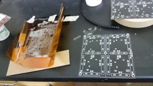
I just got in my new boards for the scoreboard project, and I was super excited to test out my plain old, unmodified toaster oven for some old fashioned reflow soldering. So I taped down the stencil and jig I had ordered from OSHStencils, and applied the solder paste to the board.
One of my first concerns when settings up this first go at reflow soldering, was how expensive the solder paste was. Well, just as i had thought, it takes very little paste to cover all the little pads. I was concerned about waste, and while there was some paste left on the stencil and the spreader tool (a plastic card that also came with the OSHStencil order), I was able to collect most of the excess paste with the tool and place it back in the container. Since this was a large board, I started with a small gob of paste and worked the board in sections, alternating between thick spreading, and scraping it back up with the edge of the card.
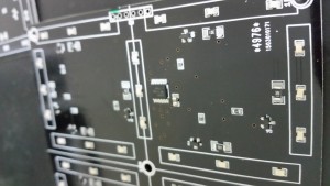
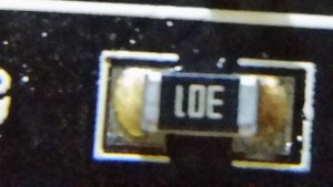
Placing the parts wasn’t too bad, I’d say it was easier than normal soldering with the 0603 resistors. I did expect the paste to be tackier, and while the parts did stick in place, it took very little effort to move them, so a stead hand is still needed to place and position. On the SOIC parts, the paste did seem to mingle between pads, but that wasn’t an issue at all. Once all the parts were down, it was into the oven.
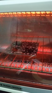
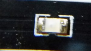
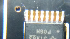
I tried to keep with the same methodology as the last post, although this time around I had black PCBs (since its an LED display, a dark background is preferred). While I’m only speculating, these boards reached much higher temperature much faster, I believe due to extra IR absorption. So this time I set the oven to 300F/150C on the convection setting (fan on). I let it heat until the thermostat clicked off, and waited until it clicked back on to turn the oven up to 400F/200C. This is were I was suprised. The black board started to flow as it approached this temperature setting, where the red board I had tested earlier flowed on its way to the 450F setting. Using a bright light, I was able to see the metallic shine of melted solder on all the joints. So once the thermostat clicked off, I shut the oven down and opened the door to let it cool. The board looked great, all the joints looked solid. There were a few were I could see that there possibly wasn’t enough paste on the pad, but the connections were still solid. The shift registers looked good, with no solder bridges.
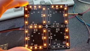
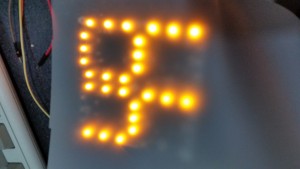
And the best part is, it worked!
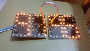
Even the digit chaining worked as expected.
I think a proper diffusing sheet would make the final product very easy to read.
And lastly, the Arduino code I used for the testing the digits.
/*
|***F***|
A       E
|***G***|
B       D
|***C***|

*/
const int D1 = 2;
const int CLK = 4;
const int STROBE = 3;

byte digitMap[10] =
{
	B11111100,
	B00011000,
	B01101110,
	B00111110,
	B10011010,
	B10110110,
	B11110110,
	B00011100,
	B11111110,
	B10011110
};


void setup()
{

	/* add setup code here */
	pinMode(D1, OUTPUT);
	pinMode(CLK, OUTPUT);
	pinMode(STROBE, OUTPUT);

	digitalWrite(STROBE, LOW);
	digitalWrite(CLK, LOW);
	digitalWrite(D1, LOW);


}

int state = HIGH;
int count = 0;
void loop()
{

	for (int i = 0; i < 100; i++)
	{
		byte Data2 = digitMap[i / 10];
		byte Data1 = digitMap[i % 10];

		//Write to display
		for (int j = 0; j < 8; j++)
		{
			digitalWrite(CLK, LOW);
			digitalWrite(D1, Data1 & 0x01);
			Data1 = Data1 >> 1;
			digitalWrite(CLK, HIGH);
		}
		//Write to display
		for (int j = 0; j < 8; j++)
		{
			digitalWrite(CLK, LOW);
			digitalWrite(D1, Data2 & 0x01);
			Data2 = Data2 >> 1;
			digitalWrite(CLK, HIGH);
		}
		delayMicroseconds(10);
		digitalWrite(STROBE, HIGH);
		digitalWrite(STROBE, LOW);

		delay(1000);
	}
}
