Yeah I know, everyone is doing it. Reflow soldering with a standard counter-top toaster oven. While it’s not too exciting, I did want to document my successful test at using a cheapo oven I picked up at Goodwill for $10, completely unmodified. I had picked this up in preparation for some boards I’m going to make as part of my scoreboard project. While I was initially going to try to go for the ever popular reflow conversion, most of the modules out there for purchase seemed quite expensive ($60+, I’m cheap, I know). My own ballpark cost of making one myself came out to be $25-$30 (less if I skip the pesky mains isolated power supply for the micro). So while looking at the unit I had acquired, I figured it was at least work testing with built in front panel controls.
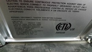
So the particular oven I picked up was a Black & Decker Toast-R-Oven 1500W, model TRO4075. Part of the reason I choose this oven over a $5 unit that was also for sale was that this one can the ‘Convection Bake’ feature, which means it includes an air circulation fan on the inside. From what I have read previously about reflowing, this can be extremely helpful for even heating and preventing hot spots.
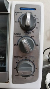
Also looking at the front panel controls, it also already had its own temperature control and timer. Before the first test, I already knew the temp control wasn’t going to be very accurate, and the timer knob resolution not really useful as the first official marking (after light and dark toast) was 10 minutes. So for the first test I simply placed a board in the oven, set the temp to the 400F/200C mark, selected convection bake, and set the timer for dark toast.
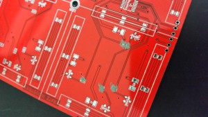
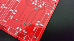
The board I used was a 10cm square board that is almost the same board that I’m going to be assembling. The board is a double digit, seven segment LED numerical display. Foolishly I hit order to quickly on the first set, and being the amateur I am, wired the three LEDs of each segment in parallel instead of series. I only noticed after I tried doing the calculations for the resistor value and power ratings did I notice that I messed it up. While technically these boards would still work, having the LEDs in parallel can lead to current imbalance that can shorted the life of the individual LEDs as well as use 3x the power of the series configuration. The only major difference in the new boards, and I’m hoping this doesn’t have to big of an effect on the infrared heating, is that the test board was DirtyPCBs.com’s default red, and my new boards are coming in with the black solder mask. My other realization was that bright red would make a terrible background for a LED display, especially with red LEDs.
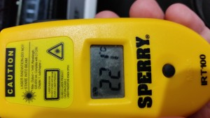
Anyways, back to the test. It was clear that the oven heats up pretty fast, probably faster than the recommended profile from the solder paste I’m planning to use. It wasn’t long before the existing solder on the pre-tinned pads began to wet. Now, I don’t have a thermocouple to measure the board temp with, so I only had my trusty el-cheapo infrared thermometer. Once the ovens own thermostat clicked the elements off, I measured the board at about 221C. Just over the melt line of the profile, but I do not have reason to suspect that the measurement was accurate by any means. I let it cook for a bit untill the timer clicked off and pulled it out of the oven after a short cool down. At first inspection all went well, no burn marks, scorching or other visible damage to the PCB. The only thing I had noticed was a bit of upward warping while the board was at peak temperature. On this board I had most of the wiring on the top layer and bottom layer is almost solid copper, so I’m guessing its a bit of thermal expansion of the bottom side that cause this. Not a big deal, it only appeared to be about a 2mm deflection at the one corner.
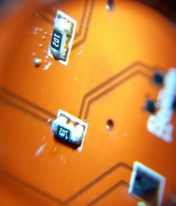
For the next test, I just wanted to see how some of my extra 0603 resistors would handle it. I didn’t break out the stencil yet, so I just dabbed some paste on 8 footprints spread about the board. Pretty ugly, but the resistors stuck to it.
In this test, I tried to follow a bit of a profile to keep the board from heating too fast. I started by setting the temp to the 300F/150C mark, then waited for the thermostat to click the elements off. I waited a few seconds, then crept the temp up the the 400F/200C mark again. I did the same by waiting for the thermostat to click off in the toaster. While this is enough melt the solder, the profile called for a peak temp of around 230-249, so for the final bit I set the temp on the toaster to its max setting, 450F/230C. After the thermostat clicked off again, I shut it down and took another temperature measurement of about 235C. I waited about 20 seconds and then removed the board from the oven to cool quickly. The results where not that bad, other than the slightly excessive amount of paste that was put down for the pads. Again no board scorching, discoloration, bubbling, or other faults. The resistors looked as though they survived as well, all measuring close to the promised 1K Ohms.
Now as soon as my new boards get here, I’m going to be ready to try out my stencil and push a few boards through.
