Introduction
As I noted in my last post, I’ve recently bought a Nikon DSLR camera, which has sparked my interest in the interchangeable lenses. Notably, trying to find cheap lenses on EBay and repairing them. I’ve gotten lucky on a couple, but even broken these lenses can still go for almost 50% of their original value, depending on the lense. And with some lenses retailing from $500-1000 USD, even a deal can be a bit pricey for the non-professional photographer. So I’m starting with the basic lenses, the common ones that are around the lower end and often come with the camera bundles. These can be had on Ebay from $20-30 including shipping if you are patient enough.
Today’s specimen is a an AF-S 18-55mm 1:3.5-5.6 VR lens. This one I got a deal on, as it was listed as “attempted to fix myself, but couldn’t do it.” Well, after receiving it, I decided this was a good one to tear completely apart, you know, for science. More specifically, to record all the internal parts, such to examine the used part market on these items, as well as to increase my understanding such that I can perform more complex repairs in the future (my first couple attempts were easy).
First, a bit of post-mortem on the part, and where the original owner messed up the repair. The listed reason for the damage was a drop. Very common, the camera is dropped (use the neck strap people!), the lens hits the ground and the plastic mount ring on the lens gives way to the metal ring on the camera. A simple repair provided the rest of the lens survives.
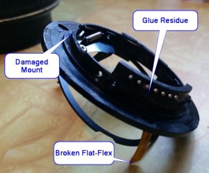
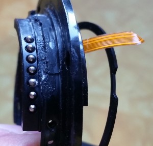
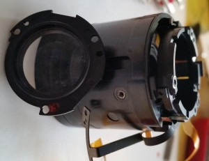
I recieved the item still in it’s dissasembled state. The mount ring is off the lens, with too glaring issues. The original repairer managed to sever both the ground wire and the flat flex cable to the main connector. You can also see evidence of the first attempt at a simple fix, as there is cyanoacrylate (SuperGlue) residue around the connector. While using glue could be considered the first mistake, as the plastic rings are very cheap to acquire, I feel their second and fatal mistake may have been an simple one. Once the rear mount ring screws are removed, the rear housing is no longer fastened to the main part of the lense. If the connector was still attached via its screws to the mount ring, they may have lifted the lens by the rear housing and, in a mear moment, the lens fell apart and the weight of the lense broke the wire and the flat flex. New replacement connectors on EBay run around $20, which is more than what I paid for the lense and almost 25% of what a similar lens would cost new/refurbished. For the purpose of repairing the lens, I may be able to clean the glue residue off and with some kapton tape and delicate soldering, maybe repair the flat flex.
Already Disassembled
Lets start with the parts that came in the box, since these are already off the lense. For info on properly removing these pieces, see my last post where I repaired a similar lens. I’ll be reusing the screw card I made in my last repair (they did include all the screws in the shipment!). Note, I’m going to be making up names for these parts, as I don’t have an official reference.
Rear Cowling
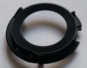
This part is located in the center of the mount ring and I think serves as a dust cover, or possibly just aestetics to the rear of the lens. It’s held by 3 screws in the mount ring.
Mount Ring
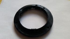
This is the rearmost part that interfaces mechanically with the camera. Three screws hold it to the lens, and two more hold the connector in place. A third screw on the inside of the lense holds a pogo-pin type connector that serves as a ground connection to the camera body via it’s metal mounting ring.
Mount Ring Shims
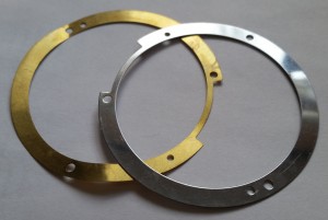
There are multiple of these parts in a thick silver and thin brass. As far as I know, these are some type of shim devices to manage how far the mount ring sticks out.
Aperture Arm
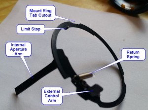
This part manages the mechanical interface to the camera body for control of the lens aperture. The small arm protrudes out the back of the lense while the long arm extends into the lens and opens/closes the aperture. The ring fits into a grove on the inside of the mount ring and the spring also anchors to the mount ring, providing a return mechanism.
Continuing with the Teardown
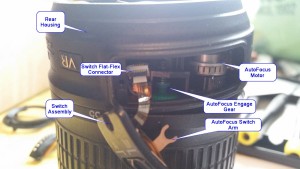
Picking up where the original owner left off, after remove the rear mount ring and associated parts (and pretending the connector was still attached), the next part to remove is the AutoFocus and Vibration Reduction switch assembly. This is attached to the rear housing by one screw, and there should be a flat flex cable holding on as well. After removing the screw and carefully lifting it off the housing, you should see the flat flex connector close to where the screw was. These seem to be a ‘flip up’ type, and the cable should remove easily after flipping the black part of the connector. This can be done with a small flat screwdriver, but be careful, as the connector is mounted on another piece of flat flex, so it will feel a bit loose.
You can remove the rear housing now, which exposes the two main electronics boards and allows you to disconnect the main connector. The flat flex connector for the main connector is a simple push/pull type without a lock, so you can just slide it out. There are two tabs on the side of the ribbon to help with that. I’m going to continue by removing the two circuit boards.
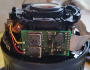
First, remove all the connectors. Pictures are helpful for reassembly, as the design is starting to get a bit ‘busy’. This can be a bit delicate for the CPU board. Note that the AF controller is wired right to the AF motor, no connectors. There is only one screw in each board, so that part is easy.
At this point the CPU is removed, but the AF controller is still attached to the AF motor. Without a better option, I’ll proceed by attempting to remove the AF motor, and its associated gears. I see two screws that seem to be holding the assembly around the motor together, so I will remove those.
Thankfully, the whole thing comes off as one piece, no gears spilling all over the place, which was a nice surprise. Now you should be able to see four screws around the inside that seem to be holding the front housing in place. This seems like a good next step.
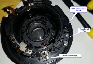
After thous are removed, the front housing is almost free, as there is a silver tab holding it in, that appears to serve as a limit for the zoom twist. Two screws hold that on, but before you remove that, there is also a silver tab holding some wiper arms, which is part of the zoom position sensor. Remove that first to avoid damaging the wiper arms. The silver zoom tab was a bit tough to get out as the arm appeared to bind in the various barrels it is intersecting with. After both of these are removed, getting the front housing off is still a bit of a challenge.
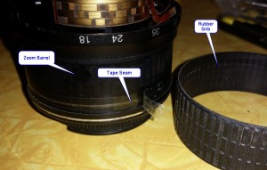
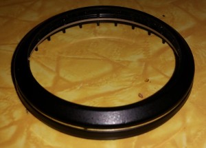
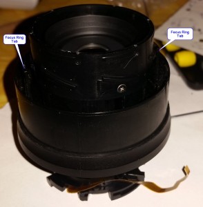
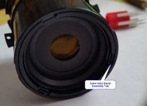
I’ll have to admit I was stuck for a bit at this point. No matter how you rotate any of the assemblies, it will not come apart. As it turns out, you need to remove the rubber grip on the outside, which exposes a tape seam on the outer zoom barrel. This certainly seems odd to me, but hey, it must work. After the tape is removed, the front part of the assembly comes off. This exposes a couple tabs, which when pulled outward, allow the front lens assembly to be rotated clockwise off of the inner lens barrel.
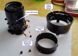
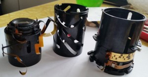
Once the front lens assembly is off, it becomes clear I had no hope of removing the outer housing. Even though loose, it was firmly trapped by an inner barrel. This appears to be attached by 3 sliver screws along its perimeter. Removing these proved to be difficult, as the screws were very tight. A good #00 or #000 phillips driver is recommended. I destroyed the first of drivers I had been using trying to free these screws. Once removed, there were also the anchors they were screwed into sitting into a channel in the inner lense assembly. These anchors may freely fall out once the autofocus helix ring is removed, and you will need to remove the anchors to make enough clearance for the zoom ring to slide off. I attach the anchors to the backs of the screws in the screw card so I don’t lose them. The zoom ring assembly also contains the focus position sensor and the sliding ring used to connect the autofocus motor to the focus ring. There doesn’t seem to be any reason to further deconstruct this part.
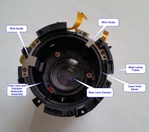
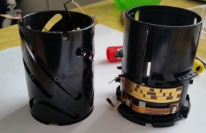
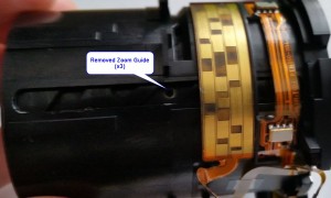
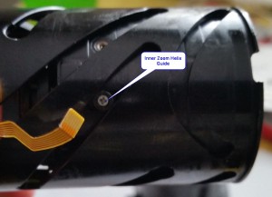
Next, looking back at the other side of the lens, we’ll remove the two metal guides that are attached at the back of the lens and follow the inner lense down inside. This won’t free the inner assembly though, as there are three screws visible along the outside of the assembly which attach posts that guide the inner assembly back and forth as the in between barrel is twisted. We’ll have to remove these to allow the inner assembly to come free. With these guides out, ensure that the metal guides and attached flat flex cables are free, because we will have to rotate the in between barrel.
There are three spots on the front of the assembly where it will have to align to slide the inner parts out.
Again now the inner lense is held into the inner helical barrel by three guides that are screwed in. We’ll have to remove these to get the lense out of the helical barrel. When these screws are removed, there are small cylinders that will pull out. The threads in these cylinders are deep and the screws sit recessed, so we can’t attach the these parts to the back of the screw sheet. You’ll have to think of a better way to not loose them. The helical barrel should slide off the inner lens.
Since I’m this far, I’m going to go ahead and keep disassembly. Next I’ll remove the rear most lense element. You’ll notice the three screws that hold this on are dabbed with some red locking glue, meaning you are probably not supposed to remove them, but at this point they are the only exposed screws. Plus the other side of that lense element is dirty and dusty. Note, that small amounts of dirt, residue, and dust typically will not affect the quality of the pictures you take. Disassembly to this point just for some cleaning would not be recommended.
When the screws are removed the lens should just pop off. Always be careful with the lens elements.
This seems like a good place to stop. While I really wanted to take a look at the vibration reduction mechanism which appears to be in the remaining assembly, I don’t seem any way to effectively continue a non-destructive tear down.
Switch Assembly
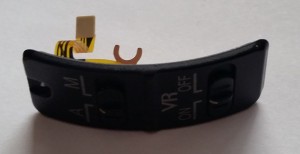
The switch assembly holds two switches for controlling the autofocus as well as the vibration reduction functions. The autofocus switch also has a mechanical part that disengages the gear for the autofocus motor to allow manual focusing.
Main Connector
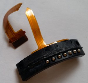
This is the electrical interface to the camera. It connects to the main board via flat flex cable. A metal piece in the back of the connector can be slid out to separate the cable from the connectors. This would aid repair if you are able to source/make just the flex circuit and reuse the connector.
CPU to AutoFocus Controller Ribbon

This is a 22 conductor flat ribbon connecting the CPU board with the autofocus controller board. Prited with part number E41447-SHC 2896 VW-1.
CPU Board

This is a 22 conductor flat ribbon connecting the CPU board with the autofocus controller board. Prited with part number E41447-SHC 2896 VW-1.
CPU Board
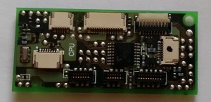
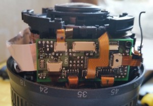
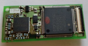
This is the main controller for the lense. There are 3 ICs on board, a custom Nikon branded BGA part (EI-134 108 H25), a larger quad flat pack (D70F3731GC V850ES/KG 1052EE247), and a small SOIC on the front (HC 4050A 049)
AutoFocus Assembly
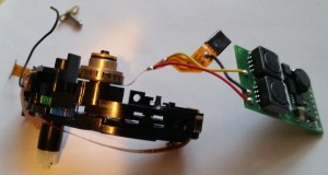
The AutoFocus comes out as a single piece, with the associated controller, piezoelectric motor and gear assembly.
Zoom Limit Tab
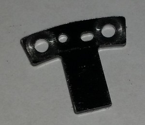
A small metal tab that appears to limit the twist of the zoom barrel.
Zoom Posistion Wiper
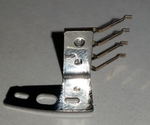
This device shorts traces on the zoom position sensor so the CPU can report the current focal length to the camera.
Grip
This rubber piece serves to provide extra grip when rotating the zoom, and to cover up the tape seam.
Front Lens Assembly
Front Lens Assembly
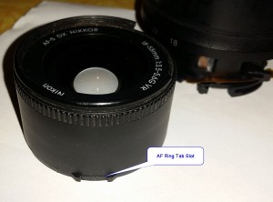
The front most lens and plastic barrel.
Autofocus Helix Ring
This part attaches to the central lens assembly and provides helical tracks to translate the rotation of the autofocus ring to linear motion of the front lens assembly.
Zoom Ring
This part forms the outside zoom ring on the lens and contains an inner ring that connects the autofocus motor the focus ring.
Inner Barrel
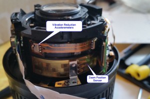
This part forms the main inner frame. It has the zoom position sensor strip and the vibration sensors attatched to it. The helical grove barrel rotates inside this part and the inner lense moves inside of that.
Inner Helical Grove Barrel
This barrel fits between the inner barrel and the lens assembly and helps translate the rotation of the zoom ring into linear motion of the inner lens.
