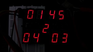
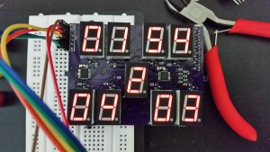
I’ve been working on a project to build a WiFi controlled scoreboard. For a display prototype, I wanted to test out a multiplexing technique for the display. Multiplexing works well for a smaller display since it only requires 16 transistors to control the 9 digits X 7 segement, or 63 LEDs. The disadvantages of multiplex approach is that you have to constantly drive the display, and the reduced brightness due to the duty cycle. For a larger display, like what I may use for the final product, I think I will just directly control the segments directly instead of the multiplex approach.
I originally believed the multiplexed method would be better, due to the reduced number of power lines to the LEDs in comparison to directly driving each segment. However in both this design and a matrix driver I built up for the large display, I used shift registers to reduce it to a serial interface. Eventually what I realized after ordering this board is that I could use the shift registers chained together to create a programmable display that would hold its state. That, and I found an economical way to do the digits as PCBs instead of some type of 3d printed affair and adhesive LED strips. The non-PCB digits is why I thought I would have to run wires to each segment individually and join them into a 8 wire bus to the common drive switches. The PCB based square double digit boards reduce that to a 6 wire (GND, V logic, V LED, CLK, Data, Latch) board to board connection. I think in the larger design where inter-digit wiring will be needed, the cost of the extra transistors (which can have a lower power rating than the multiplex drives) will be more than offset by the cost and complexity of the extra wiring.
The design here is pretty simple, I’m just using 2 standard 74LS595 latching shift registers to feed data into the display. The latching feature is important, because in this application we don’t want the bits to just be shifting along the outputs. On the latch step, the internal 8 bit shifter is copied to the outputs all at once. There are 9 common anode 7 segment displays (I’m not using the dot), which works out to need exactly 16 bits. I’m using NPN transistors to both sink and source current to the display. See the schematic linked below. The code below is just some example code of feeding data to the display. You just have to clock the bits out to each of the shift registers and then latch the outputs. I didn’t chain the registers together, so there are 2 inputs to feed data two simultaneously, as the clock and latch pins are shared on the board. The code uses an array of bytes to map which bits to turn on for each number. One important note I had trouble with on the first attempt, data is clocked in on a low to high rising edge, but an additional high to low falling edge was required before latching, or else the final bit would never change. That doesn’t make much sense, so its possible it was just a timing issue and the extra port write gave the register enough time to settle before latching. The code was tested with the Arduino compiler using the VisualMicro Visual Studio Plugin.
/*
	|***A***|
	F	    B
	|***G***|
    E       C
	|***D***|

	D1 A-G, Com9
	D2 Com1 - Com8

*/
const int D1 = 2;
const int D2 = 3;
const int CLK = 5;
const int STROBE = 4;

byte digitMap[10] =
{
	B11111100,
	B01100000,
	B11011010,
	B11110010,
	B01100110,
	B10110110,
	B10111110,
	B11100000,
	B11111110,
	B11100110
};


int Score1 = 4;
int Score2 = 3;

int Min = 2;
int Sec = 0;

int Period = 2;

void setup()
{

  /* add setup code here */
	pinMode(D1, OUTPUT);
	pinMode(D2, OUTPUT);
	pinMode(CLK, OUTPUT);
	pinMode(STROBE, OUTPUT);

	digitalWrite(STROBE, LOW);
	digitalWrite(CLK, LOW);
	digitalWrite(D1, LOW);
	digitalWrite(D2, LOW);


}

int state = HIGH;
int count = 0;
void loop()
{

	for (int i = 0; i < 9; i++)
	{
		byte Data2 = B10000000 >> i;
		byte Data1 = getBits(i);
		if (i == 8) Data1 |= B00000001;

		//Write to display
		for (int j = 0; j < 8; j++)
		{
			digitalWrite(CLK, LOW);
			digitalWrite(D1, Data1 & 0x01);
			digitalWrite(D2, Data2 & 0x01);
			Data1 = Data1 >> 1;
			Data2 = Data2 >> 1;
			digitalWrite(CLK, HIGH);
		}
		digitalWrite(CLK, LOW);
		digitalWrite(STROBE, HIGH);
		digitalWrite(STROBE, LOW);

	}
	count++;
	if (count > 0x0FF0)
	{
		if (Sec == 0)
		{
			Sec = 59;
			Min -= 1;
		}
		else
			Sec -= 1;
		count = 0;
	}


}

byte getBits(int digit)
{
	switch (digit)
	{
	case 0:
		return digitMap[Min / 10];
	case 1:
		return digitMap[Min % 10];
	case 2:
		return digitMap[Sec / 10];
	case 3:
		return digitMap[Sec % 10];
	case 4:
		return digitMap[Period];
	case 5:
		return digitMap[Score1 / 10];
	case 6:
		return digitMap[Score1 % 10];
	case 7:
		return digitMap[Score2 / 10];
	case 8:
		return digitMap[Score2 % 10];
	}

}


Pingback: An Experiment In Shift Registers and Multiplexed LEDs | Hackaday
Pingback: Tech News / An Experiment In Shift Registers and Multiplexed LEDs
Pingback: An Experiment In Shift Registers and Multiplexed LEDs | MyWebspace
Pingback: An Experiment In Shift Registers and Multiplexed LEDs | 0-HACK
Pingback: An Experiment In Shift Registers and Multiplexed LEDs - zeax blog (ze-ax.com)