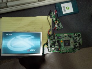
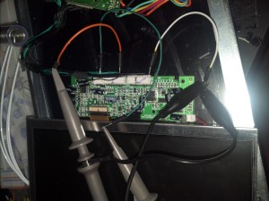
I recently picked up this old portable DVD player marked “Doesn’t Work” for cheap at the local junk shop. My intent was to figure out the LCD interface and attempt to drive the display. This article is just the investigation. Once removed from the player, the LCD module and backlight is contained in a metal can, connected via a flat-flex to a small interface board, which conveniently contains the back-light driver as well. Its probably easier to just use the provided interface, so I examined the signals going into that. Luckily, the screen still worked perfectly, and I was able to power up the device outside of the body in order to get my scope on the pins. There were 24 pins in total, and helpfully, there where 23 labels on the rear silkscreen of the interface board. The below table shows those pins from top to bottom of the board (the side with the 4 pin connector at the top), along with the labels and my findings. I’m using an old 20MHz analog scope, so some of the measurements may not be precise.
Also, be sure to set your probes to x10 for high speed measurements. More info here.
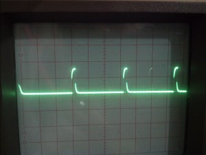
| TFT_STH | High pulse every 64uS, very short pulse. Based on the PCB label and speed, I’ll call this ‘Horizontal Strobe’. |
| TFT_STV | High pulse every 17mS, very short pulse. ‘Vertical Strobe’. Note that this timing shows about 265 ish Horizontals per Vertical. Also this implies 60 FPS. |
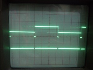
| CKV | 4uS High pulse every 64uS. This pulse edge is 12uS before STH. ‘Vertical Clock’. |
| OEV | 4uS High pulse every 64uS. This pulse edge is 4uS before CKV. ‘… Vertical’ |
| — | — |
| OEH | 4uS Low pulse every 64uS. The edge is 2uS after CKV. ‘?’ |
| GND | Ground |
| CPH1 | .1uS Squarish Wave. About 10 MHz. As the fastest signal. I’m guessing this is the Pixel Clock. Not sure if the wave appearance is the fault of the scope, of if more is going on in there. |
| GND | Ground |
| 89P_VCOM | 128uS Square Wave. Transitions in the middle of the CKV pulse. Seems to alternate high low every other line. |
| GND | Ground |
| TFT_R | Pixel data. Red. Couldn’t trigger on signal, but has patterns that align with pixel clock and CKV. Analog signal. |
| TFT_G | Pixel data. Green. Couldn’t trigger on signal, but has patterns that align with pixel clock and CKV. Analog signal. |
| TFT_B | Pixel data. Blue. Couldn’t trigger on signal, but has patterns that align with pixel clock and CKV. Analog signal. |
| GND | Ground |
| — | — |
| GND | Ground |
| GND | Ground |
| VCC | +5V |
| BLVCC | +5V. Must be for backlight. |
| GND | GND |
| GND | GND |
| TFT+5V | +5V |
| +5VPV | +5V |
| GND | GND |
That actually paints a pretty cloudy picture of whats going on. Mostly because I cannot find the specs for this screen, so I’m going to have to guess the resolution. The vertical strobe shows that around 265 lines are transmitted per vertical clock pulse. That sounds like a good vertical resolution, but at 17mS per vertical strobe, that’s about 60 FPS. So there must be some kind of interleaving of data somewhere. That makes sense because the 89P_VCOM line alternates high/low for every other line. Possibly some type of high byte/low byte scenario? I ran the screen while holding this pin low, and the image became washed out. So its a possibility. Since each horizontal strobe is 64uS, and the pixel clock is .1uS, this shows about 640 bits per RGB channel per line. Now, 640 sounds like a reasonable horizontal resolution. Originally this had me confused as I assumed the RGB pixel data signals were digital, when they were actually analog.
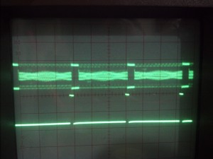
That’s about all the info I can gather for now. I won’t be able to tell if my assumptions are accurate until I hook it up to something. I’ll end with my scope readings for those playing along at home.
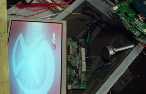
I was able to confirm that the RGB lines going into the panel are in fact analog. I attached a potentiometer between 5V and ground to form a simple voltage divider and attached the tap to the Red line. Turning the knob I was able to adjust the Red level of the image.
