I was just recently aquired an 8×8 RGB LED matrix, similar to this one. I though it would be good practice to wire up the Papilio board to it an write up some VHDL to drive the display.
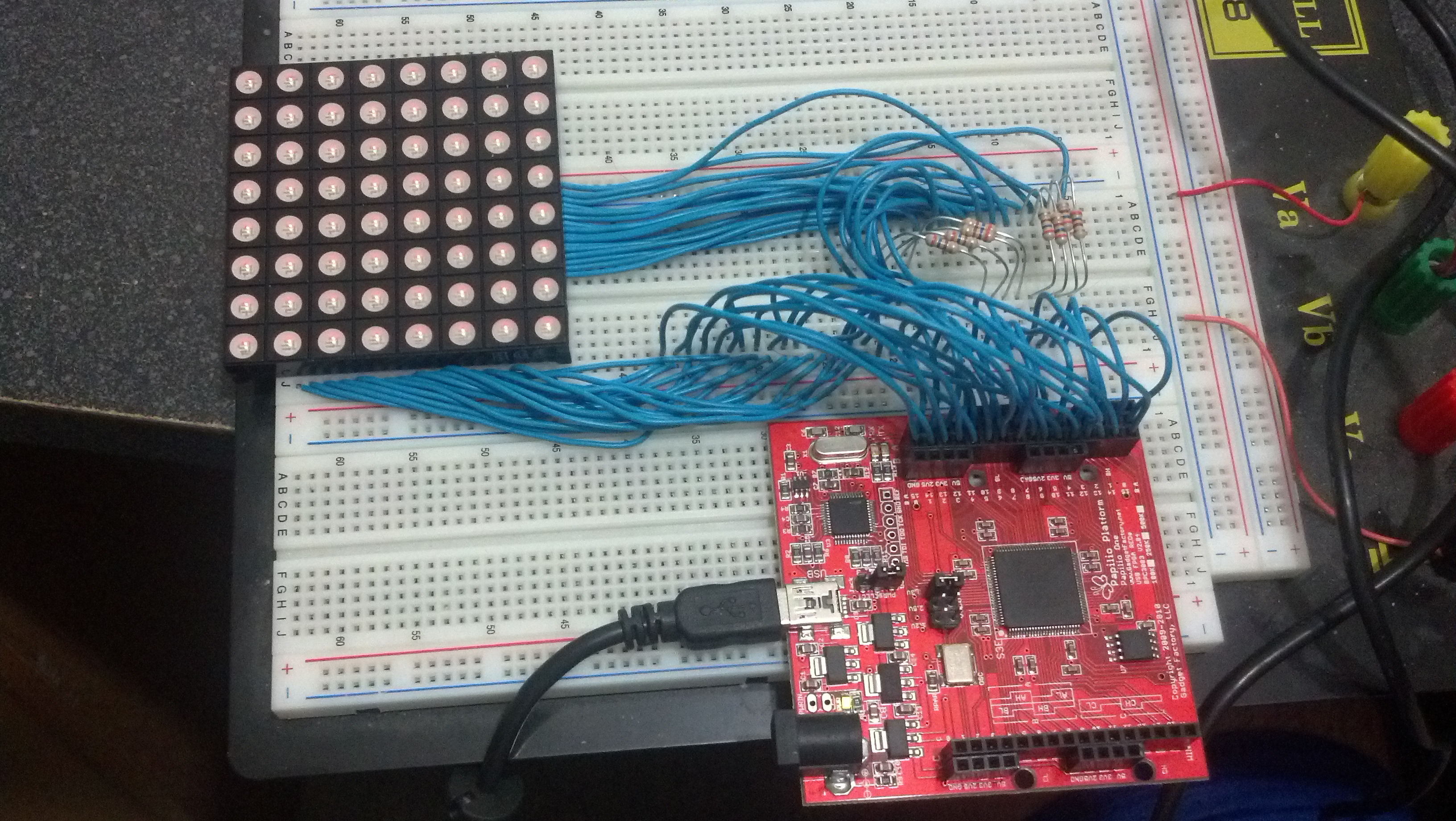
As you can see on the datasheet, this is a common anode display, meaning that the positive voltage will be supplied to the 8 common terminals to operate. The pinout is pretty simple, 1 through 8 are the blue cathodes, which I connected to pins B0-B7 on the board. 9 through 16 are the green cathodes, which are connected to pins A8-A15 board. Pins 21 through 28, are the red cathodes and are connected to the boards B15-B8 pins. Pins 17,18,19,20,29,30,31,32 are the anodes and are connected to pins A0-A7 on the board. I included some small 360 ohm resistors on the anodes, just to limit the current. However the LEDs are not very bright as such. Its much brighter, and I *think* it’s safe to drive the outputs directly from the pins. Otherwise some simple buffer drivers I’m sure would produce a much brighter result.
As for the code, I started off with some of the same stuff from the last LED matrix. The PWM drive is the same, but I changed the counter from 8 bit to 4 bit. It simply counts up, and as long as the counter is less than the set value, the output bit is on.
library IEEE;
use IEEE.STD_LOGIC_1164.ALL;


entity PWM is
    Port ( Value_In : in  integer range 0 to 15 ; --input for pwm value
           Bit_Out : out  STD_LOGIC;					--pwm output
			  clk : in STD_LOGIC);							--system clock
end PWM;

architecture Behavioral of PWM is

begin

	pwm: process(clk)
		variable count: integer range 0 to 15 := 0; --variable, internal to process, 8 bit counter
	begin
		if rising_edge(clk) then
			--increment count variable (note variable uses := not <=
			count := count + 1;

			if count < Value_In then
			   --while the counter is less than value, set bit
				--this ensures duty cycle is proportional to value
				Bit_Out <= '1';
			else
				--off during other half of cycle, while counter is greater than value
				Bit_Out <= '0';
			end if;

		end if;

	end process;


end Behavioral;
For the main code, I decided to just have it display all one color, where the RGB values are cycled through at different rates. I also tried to pull out as much as I could from the main process block, to avoid some of the confusion of values being set after the process completes, which caused actions to be one step behind where I thought they would be. The way I understand it, statements in the architecture block are “wired up” so that changes propagate almost instantly. I added three processes to handle the cycling of the RGB values. The signal ‘counter’ just serves as a delay to time the scanning process. The signal ‘row’ is a 24 bit mask for the cathode pins, where the 0 indicates the pin that is active. The signal ‘col’ is an 8 bit mask for the anode pins, where 1 indicates the active pin. The signal ‘rgb’ is a 3 bit flag which is rotated to keep track of which value, red, green, or blue, should be applied to the currently active cathode pin. ‘col’ is rotated left whenever ‘counter’ rolls back to zero, ‘row’ and ‘rgb’ are rotated left when after ‘col’ is rotated back to its original value. A WITH … SELECT syntax is used to map the different color values into ‘value’ depending on the value of ‘rgb’. ‘value’ is mapped into the PW generator, and ‘pwm_bit’ is mapped as its output. A WHEN … ELSE style assignment is used to enable or disable the ‘col’ flags on the output, which is what ties the PWM drive to the output.
--Standard includes
library IEEE;
use IEEE.STD_LOGIC_1164.ALL;
use IEEE.STD_LOGIC_ARITH.ALL;
use IEEE.STD_LOGIC_UNSIGNED.ALL;

--Entity definiton
entity First is
    Port ( A : out  STD_LOGIC_VECTOR (15 downto 0); -- maps to pins 0 to 16 of port A
				B : out STD_LOGIC_VECTOR (15 downto 0); --
			  clk : in STD_LOGIC); --clock signal
end First;

--architecture definition
architecture Behavioral of First is

--component definition for the PWM
component PWM is
    Port ( Value_In : in  integer range 0 to 15 ;
           Bit_Out : out  STD_LOGIC;
			  clk : in STD_LOGIC);
end component;

 --Interial signals
 --counter to control state and delay
 signal counter : STD_LOGIC_VECTOR(8 downto 0) := (others => '0');
 --signal for LED "rows", anodes. 0 provides ground for selected row
 signal row : STD_LOGIC_VECTOR(23 downto 0) := "111111111111111111111110";
 --signal for LED "columns", common cathodes. 1 provides + volts for selected column.
 signal col : STD_LOGIC_VECTOR(7 downto 0) := "00000001";				--signal for LED columns

 --rgb flag, for selecting R,G,B values to send to selected output
 signal rgb : STD_LOGIC_VECTOR(2 downto 0) := "001";

 --rolling color values
 signal red_value : integer range 0 to 15 := 0;
 signal green_value : integer range 0 to 15 := 0;
 signal blue_value : integer range 0 to 15 := 0;
 --used to retrieve value from array, mapped to PWM input
 signal value : integer range 0 to 15 := 0;

 --counters for timing color changes
 signal red_counter : STD_LOGIC_VECTOR(20 downto 0) := (others => '0');
 signal green_counter : STD_LOGIC_VECTOR(19 downto 0) := (others => '0');
 signal blue_counter : STD_LOGIC_VECTOR(18 downto 0) := (others => '0');

 --signal to be mapped to PWM output
 signal pwm_bit : STD_LOGIC;

begin

	--port map for linking to the PWM
	PW1 : PWM port map(Value_In => value,
							 Bit_out => pwm_bit,
							 clk => clk);


	--route row masks to outputs
	A(15 downto 8) <=  row(22) & row(19) & row(16) & row(13) & row(10) & row(7) & row(4) & row(1); -- green
	B(15 downto 8) <= row(21) & row(18) & row(15) & row(12) & row(9) & row(6) & row(3) & row(0); -- red
	B(7 downto 0) <= row(23) & row(20) & row(17) & row(14) & row(11) & row(8) & row(5) & row(2); -- blue

	--route column masks to outputs, only if PWM bit is on
	A(7 downto 0) <= col WHEN pwm_bit = '1'
								ELSE "00000000";

	--route proper RGB value to PWM generator
	WITH rgb SELECT
		value <= red_value WHEN "001",
					green_value WHEN "010",
					blue_value WHEN "100",
				   0 WHEN OTHERS;


	--Process Definition
	scan_matrix: process(clk)
   begin
		-- triggers action on rising edge of clock signal
     if rising_edge(clk) then
	    --increment counter
       counter <= counter+1;
		 --clock period is 31.25ns, counter is 9 bits, should scan whole matrix in < 1ms
			--trigger each time counter rolls over back to zero
			if counter = 0 then
				-- Left Rotate col
				col <= col(6 downto 0) & col(7);

				-- Trigger when last column becomes active
				if col = "10000000" then
					-- Left rotate row
					row <= row(22 downto 0) & row(23);
					-- increment row count
					rgb <= rgb(1 downto 0) & rgb(2);

				end if;

			end if;

     end if;
   end process;


	--Process Definition
	red: process(clk)
   begin
		-- triggers action on rising edge of clock signal
     if rising_edge(clk) then
			red_counter <= red_counter + 1;
			if red_counter = 0 then
				red_value <= red_value + 1;
			end if;
	  end if;
	end process;

	  	--Process Definition
	blue: process(clk)
   begin
		-- triggers action on rising edge of clock signal
     if rising_edge(clk) then
			blue_counter <= blue_counter + 1;
			if blue_counter = 0 then
				blue_value <= blue_value + 1;
			end if;
	  end if;
	end process;

		--Process Definition
	green: process(clk)
   begin
		-- triggers action on rising edge of clock signal
     if rising_edge(clk) then
			green_counter <= green_counter + 1;
			if green_counter = 0 then
				green_value <= green_value + 1;
			end if;
	  end if;
	end process;


end Behavioral;
tnx dear…pls talk about 16*32 RGB led panels. These panels require 12 digital pins (6 bit data, 6 bit control)…like this https://www.adafruit.com/product/420