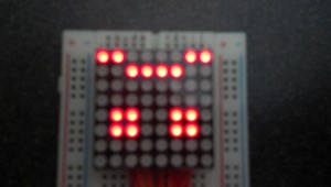
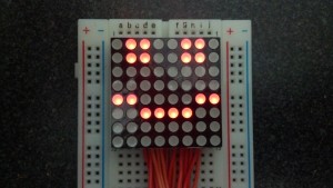
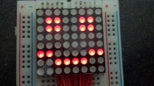
In the second part of this article, we’re going to try and get a little more interesting stuff going on with our FPGA powered LED matrix. To start, we will try to get a simple image to display on the matrix. To do this we will need a way to store the image. VHDL allows for array types so we can accomplish this by creating an eight element array of eight bit vectors, giving us one bit per pixel. We can then use each of these vectors as a mask value to AND with the col signal. This is a little confusing (at least in my head), as each col value contains a bit for each row in the column, so we AND that with the col_mask value, which is essential the pixels for a row of the display. Starting with the same setup from last time, we are adding these new signals to the architecture.
 type display_t is array(7 downto 0) of STD_LOGIC_VECTOR(7 downto 0);
 signal display : display_t := ("00000000" ,    -- A simple image to display
											"01100110" , 	-- stored in an array
											"01100110" ,
											"00000000" ,
											"00000000" ,
											"11000011" ,
											"00111100" ,
											"00000000");

 signal col_mask : STD_LOGIC_VECTOR(7 downto 0) := "00000000";		--mask value used to activate only desired pixels
 signal row_count : unsigned(2 downto 0) := "000";						--pointer for array
Note that for the array, you have do declare an array type first, then declare an array of that type. Like many languages, we are allowed to instantiate the array with some values. Notice the nice smiley face. Also note that the array is declared 7 downto 0, meaning the first element essentially is the last one in the instantiation list. Since row 0 of our display is at the bottom, this means the image should appear just as the bits appear in the code. I also added a row_count signal, declared as unsigned because it will be used numerically. This will just count up as we scan the matrix rows and serve as a pointer to our array. Also added is the col_mask signal. This signal stores the current row loaded from the array. Below is the added code to increment the row_count and retrieve the col_mask. Note that the row_count is declared as 3 bits, meaning it will automatically rollover back to zero after 7.
					-- increment row count
					row_count <= row_count + 1;
					-- get column mask from current position in array
					col_mask <= display(conv_integer(row_count));
And then of course we AND the mask to the output.
			--combine column with mask to only display selected pixels
			A(15 downto 8) <= (col AND col_mask);
Here is the complete code for this example.
--Standard includes
library IEEE;
use IEEE.STD_LOGIC_1164.ALL;
use IEEE.STD_LOGIC_ARITH.ALL;
use IEEE.STD_LOGIC_UNSIGNED.ALL;

--Entity definiton
entity First is
    Port ( A : out  STD_LOGIC_VECTOR (16 downto 0); -- maps to pins 0 to 16 of port A
			  clk : in STD_LOGIC); --clock signal
end First;

--architecture definition
architecture Behavioral of First is
 --Interial signals
 signal counter : STD_LOGIC_VECTOR(8 downto 0) := (others => '0'); --counter to control state and delay
 signal row : STD_LOGIC_VECTOR(7 downto 0) := "11111110";				--signal for LED rows
 signal col : STD_LOGIC_VECTOR(7 downto 0) := "00000001";				--signal for LED columns
 type display_t is array(7 downto 0) of STD_LOGIC_VECTOR(7 downto 0);
 signal display : display_t := ("00000000" ,    -- A simple image to display
											"01100110" , 	-- stored in an array
											"01100110" ,
											"00000000" ,
											"00000000" ,
											"11000011" ,
											"00111100" ,
											"00000000");

 signal col_mask : STD_LOGIC_VECTOR(7 downto 0) := "00000000";		--mask value used to activate only desired pixels
 signal row_count : unsigned(2 downto 0) := "000";						--pointer for array

begin
	--Process Definition
	count: process(clk)
   begin
		-- triggers action on rising edge of clock signal
     if rising_edge(clk) then
	    --increment counter
       counter <= counter+1;
		 --clock period is 31.25ns, counter is 9 bits, should scan whole matrix in < 1ms
			--trigger each time counter rolls over back to zero
			if counter = 0 then
				-- Left Rotate col
				col <= col(6 downto 0) & col(7);
				-- Trigger when last column becomes active
				if col = "10000000" then
					-- Left rotate row
					row <= row(6 downto 0) & row(7);
					-- increment row count
					row_count <= row_count + 1;
					-- get column mask from current position in array
					col_mask <= display(conv_integer(row_count));
				end if;
			end if;
			--copy signals to outputs
			A(7 downto 0) <= row;
			--combine column with mask to only display selected pixels
			A(15 downto 8) <= (col AND col_mask);
     end if;
   end process;


end Behavioral;
This give the following output.
Now if you noticed, it looks good, but that’s not the image we intended. Its shifted up by one row! See my question on Stack Overflow for an explanation of where I went wrong. Apparently signals are updated at the end of the process, so the value is definitely updated after the value is retrieved from the array. The fix is pretty simple, I just instantiate my row_count to 1 to compensate.
signal row_count : unsigned(2 downto 0) := "001"; --pointer for array
Now it displays correctly.
Now for one more experiment in this installment, lets create a vertical scrolling effect. In the above example where I screwed it up the first time, having the wrong value for row_count shifts the image up and down. We can use this to create our scrolling effect. My first thought was to add a second process with a delay counter and just subtract one from the row_count value. However, that produces a compile error, “this signal is connected to multiple drivers.” I’m guessing that means its illegal to set a signal from multiple processes. So, instead we will add a new signal, row_offset, same type as row_count. Then we will use the second process to increment that, and just subtract it from row_count when indexing the array.
We add these two new signals.
 signal row_offset : unsigned(2 downto 0) := "000";					--offset to control vertical scrolling
 signal scroll_delay : STD_LOGIC_VECTOR(22 downto 0) := (others => '0'); --counter for vertical scroll delay
And we add this new process to the same architecture.
	vscroll: process(clk)
		begin

			if rising_edge(clk) then
				--counter is 23 bits, will rollover at .26 seconds
				scroll_delay <= scroll_delay+1;

				if scroll_delay = 0 then
					--decrement to mis-align row count, to give a vertical scrolling effect
					row_offset <= row_offset+1;
				end if;
			end if;
		end process;
The we modify the array access like this.
					-- get column mask from current position in array
					col_mask <= display(conv_integer(row_count) - conv_integer(row_offset));
I had to use the two separate conv_integer functions as the compiler complained of trying to do the math first, then calling conv_integer. Here is the complete code.
--Standard includes
library IEEE;
use IEEE.STD_LOGIC_1164.ALL;
use IEEE.STD_LOGIC_ARITH.ALL;
use IEEE.STD_LOGIC_UNSIGNED.ALL;

--Entity definiton
entity First is
    Port ( A : out  STD_LOGIC_VECTOR (16 downto 0); -- maps to pins 0 to 16 of port A
			  clk : in STD_LOGIC); --clock signal
end First;

--architecture definition
architecture Behavioral of First is
 --Interial signals
 signal counter : STD_LOGIC_VECTOR(8 downto 0) := (others => '0'); --counter to control state and delay
 signal row : STD_LOGIC_VECTOR(7 downto 0) := "11111110";				--signal for LED rows
 signal col : STD_LOGIC_VECTOR(7 downto 0) := "00000001";				--signal for LED columns
 type display_t is array(7 downto 0) of STD_LOGIC_VECTOR(7 downto 0);
 signal display : display_t := ("00000000" ,    -- A simple image to display
											"01100110" , 	-- stored in an array
											"01100110" ,
											"00000000" ,
											"00000000" ,
											"11000011" ,
											"00111100" ,
											"00000000");

 signal col_mask : STD_LOGIC_VECTOR(7 downto 0) := "00000000";		--mask value used to activate only desired pixels
 signal row_count : unsigned(2 downto 0) := "001";						--pointer for array
 signal row_offset : unsigned(2 downto 0) := "000";					--offset to control vertical scrolling
 signal scroll_delay : STD_LOGIC_VECTOR(22 downto 0) := (others => '0'); --counter for vertical scroll delay

begin
	--Process Definition
	count: process(clk)
   begin
		-- triggers action on rising edge of clock signal
     if rising_edge(clk) then
	    --increment counter
       counter <= counter+1;
		 --clock period is 31.25ns, counter is 9 bits, should scan whole matrix in < 1ms
			--trigger each time counter rolls over back to zero
			if counter = 0 then
				-- Left Rotate col
				col <= col(6 downto 0) & col(7);
				-- Trigger when last column becomes active
				if col = "10000000" then
					-- Left rotate row
					row <= row(6 downto 0) & row(7);
					-- increment row count
					row_count <= row_count + 1;
					-- get column mask from current position in array
					col_mask <= display(conv_integer(row_count) - conv_integer(row_offset));
				end if;
			end if;
			--copy signals to outputs
			A(7 downto 0) <= row;
			--combine column with mask to only display selected pixels
			A(15 downto 8) <= (col AND col_mask);
     end if;
   end process;

	vscroll: process(clk)
		begin

			if rising_edge(clk) then
				--counter is 23 bits, will rollover at .26 seconds
				scroll_delay <= scroll_delay+1;

				if scroll_delay = 0 then
					--decrement to mis-align row count, to give a vertical scrolling effect
					row_offset <= row_offset+1;
				end if;
			end if;
		end process;


end Behavioral;
And here is the scrolling effect in action.

Next time we will see about making a simple animation with several frames. See you then!


hey really nice write up, I’m actually doing something similar to this for my class project but kind of stuck, was wondering if you can help. i want to use 17 inputs (switches) to represent 17 letters, each switch will have 1 letter assigned to it. was wondering if you can help me out.
thanks
Thanks for the comment!
Off the top of my head, I’m thinking a simple modification to the scrolling display example might fit your need. Extend the display array to such that it contains all of your letters. Then you can use the row_offset to create a sliding window effect for the display rather than a scrolling effect. So instead of just incrementing the row_offset, you can check the state of your inputs and set the offset to the appropriate spot in the display array for the desired letter.