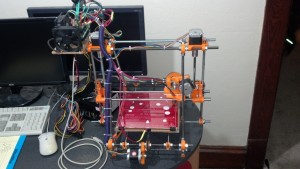
Recently, I had the pleasure of putting together my first 3D printer, a design by the RepRap project.
One of the more important aspects of the build is acquiring a power capable of driving at least 16 amps at about 12 volts. The cheapest solution usually used, is the humble ATX power supply. Mass produced for the desktop PC market, they can supply high current at common voltages, and are available everywhere. The ATX supply is easily converted to power the RepRap hardware, and that info is covered on their wiki. I quickly found a supply off of NewEgg, specifically, this one. Featuring 25 amps of output on the 12 volt rail, and only $20, this fit the bill quite nicely. However, once I got everything hooked up and did a few test prints, I had one slight problem. The power supply would, seemingly randomly, shut itself off, ruining my print.
The first attempts to correct this followed advice on the wiki and in many forum posts. The recommendation was to put a significant load, 1 or 2 amps, on the 5 volt rail of the power supply. The theory goes that, depending on how the supply was designed, it expects most of the load to go to the 5 volt rail, as it would if it was hooked to the computer system it was designed to power. This can cause significant voltage drop on the 12 volt rail when its loaded without load on the 5 volt rail, causing the supply’s internal protection circuit to shut down the supply. Following this advice, I hooked a couple large 1 ohm power resistors in series, glued them to some aluminum head sinks, to give a nice 2.5 amp load for the 5 volt rail. Unfortunately, this failed to solve the issue.
I decided to Google around to see how easy it would be to simply disable the safety features of the power supply, and I found an interesting article. Interestingly, these guys were powering 12 volt audio amplifiers at high current, and running into the same problem as me. Reading the article revealed that shutdown protection was controlled by a single IC inside the supply, and could easily be controlled by grounding some pins. Now, the supply they were modding didn’t have the control chip as the supply I had, and that led me to their source article, here, and the datasheet for the chip I found in my supply.
The final fix took several iterations to get right. The simple fix in the article, grounding pin #4 to disable all under voltage protection for all rails, just didn’t work for me. The supply still shut itself down. After reading into the datasheet, I learned that the IC monitors the voltages on the main rails, 3.3, 5, and 12v. It monitors these voltages through pins 1,2, and 3. The datasheet revealed that simply grounding these pins disables the monitoring for both under and over voltage conditions, which should prevent it from shutting off spontaneously. Normally, not what you would want, but some aspect of the printer, the motors or the heat bed, must have been producing voltage spikes that were accidentally tripping this protection. This change turned out to be pretty easy, since the datasheet showed that pin #5 was ground, so it was just a matter of connecting pins 1,2,3,4, and 5 together, and cutting the traces to pins 1-4. Once I did this, viola! My printer has been working without shutting down since.
Here’s a view of the top of the control IC on the ATX single sided PCB.
Here is a view of the changes I made. As you can see, I just used a sharp pointy object to scratch away at the PCB till I was sure the traces leading to pins 1-4 were all cut. I had to add the blue wire, because the one trace ran past the pin and to another spot. The red wire was coming off the ground pin to pin #4. After that I decided just to solder bridge to the rest of the pins.


Thank you for this hack ! That one will serve me for the rest of my life
Same problem, same solution 🙂
Thank you for posting this.
Hi, thanks for your post. Unfortunately I have the same Problem. Not especially when heating the bed but when the motors start moving to the middle the power supply shuts down sometimes. Unfortunately in my Power supply there is the TPS3510P chip which controls the voltage. Does anyone know something about it?
I found a data sheet here,
http://pdf1.alldatasheet.com/datasheet-pdf/view/29206/TI/TPS3510P.html
It looks like the FPO pin goes high to signal a shutdown. You could try cutting that pin, since the datasheet says its an open collector output.
Does anyone know how to do this with a TSM1002DS best thing i’ve found for this is someone saying it’s a none consumer chip that was specifically only made for PSU companys to use in house so no public data sheets can be found
You are right for such IC 8010, 7520, 2921 etc as shown in your datasheet . After joining the pin 1,2,3,4 to ground pin 5
you don’t even need to cut the pins connection from the PCB. You can change the Volt output by removing the output connection of + 5 volt to pin sixteen & adding a potentiometer in series with pin + 12 volt and between pin sixteen of course with changing of the volts of output caapcitors!